Digital Ding Dong Ditch is a device I created to hack into and ring my best friend's wireless doorbell whenever I send a text message to the device. The best part of the device is that it causes my friend, without fail, to come outside, find no one, and go back in.
In this project, we'll learn not only how to create this device, but how to reverse engineer radio frequencies we know nothing about using RTL-SDR (a ~$14 software defined radio), as well as creating hardware and software using Arduino, the Adafruit FONA (GSM/SMS/2G board), an RF (radio frequency) transmitter to transmit custom signals, and even how to reverse engineer a proprietary radio signal we know nothing about!
by @SamyKamkar // code@samy.pl // https://samy.pl // Dec 11, 2014
Code available on github
My best friend Matt (we call him "donr") mentioned to me the other day that his doorbell was wireless. Incredible!
While he was away from his house, I decided to drive to his house and:
Amazing. Hopefully we'll still be friends after this. I can now ring his doorbell no matter how far away I am from his house, and he will never see my device as it's hidden across the street wirelessly manipulating his home.
Through this project, I'm going to explain from start to finish how I determined, hacked, reverse engineered, and built each piece and joined them together into this fun project, as well as provide schematics, source code, and explanation from start to finish.
You can acquire the Digital Ding Dong Ditch source code from my github: https://github.com/samyk/dingdong
This is an Arduino sketch which uses the hardware mentioned below.
You should use my version of the Adafruit FONA library as I include an additional option that allows the FONA to let us know when there's a new text message. In the original library, you must constantly poll to see if there are more text messages than you expect, however with my version you can enable an option fona.setSMSInterrupt(1) which causes the RI (Ring Interrupt) pin to pull low for a moment upon new SMS messages.
For Linux or Mac, you can use GQRX, or for Windows, SDRSharp. These allow you to have GUI interfaces to visualize and listen to signals through your RTL-SDR device. Any program that interfaces with RTL-SDR to see an FFT or waterfall view of the spectrum will suffice.
We use the RTL-SDR codebase to listen and save the signal (via rtl_fm), however you can simply use GQRX or SDRSharp mentioned above to save the signal if you prefer.
Audacity is a free application for audio file modification. We use it to look at and interpret the radio signal.
$14: RTL-SDR is an extremely inexpensive software defined radio (SDR) using a chip from Realtek (RTL). If you have any idea why all Realtek devices are labeled RTL, rather than RLT, please email me as it really bothers me.
Anyway, you can get these dongles new around $14-20. These great chips allow you to receive full I/Q samples of radio frequencies down to potentially 22MHz up to around 2.2GHz, which includes all sorts of interesting radio frequencies! Cars! Garages! Doorbells! Glucometers! Medical devices! Pagers! Cell phones! Wireless phones! Broadcast TV! Airplanes! Power meters! Two way radios! Did I mention pagers? Don't page me, bro. Any RTL-SDR device with decent reviews on Amazon should suffice.
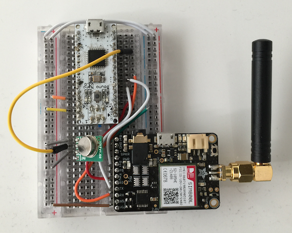
$6: Arduino is an awesome platform for software and hardware development and allows rapid creation of hardware. We'll be using an Arduino Nano clone specifically, however almost any Arduino microcontroller should work. Other microcontrollers or other devices capable of serial communication such as the Raspberry Pi, BeagleBone Black, raw Atmel chip or any other reasonable microcontroller should be able to do what we're doing here.
$4: I use an inexpensive ($4) 434MHz ASK RF transmitter from SparkFun for this project. Note that this device entirely depends on the frequency and modulation of the device you're attempting to transmit to. I knew to get this transmitter only after I determined Matt's doorbell was using the radio frequency of ~434MHz (see how we determine this below or watch the video) and that the digital modulation was ASK, which is a type of digital amplitude modulation (AM). You can see the datasheet here.
OPTIONAL ($45): Adafruit created an awesome board called the FONA which allows you to drop in a 2G SIM card and send/receive SMS's, phone calls, and even use the Internet directly from this little device and a microcontroller. Look ma', I'm on the information super highway!
If you obtain this, you'll be able to send a text message to your Arduino to send the signal, however if you're not looking to have this sort of setup, no problem, I include a version of software without any GSM board where the Arduino simply (read: annoyingly) rings the doorbell every 30 seconds without any text message or FONA board required!
OPTIONAL ($3, only if using FONA): The FONA requires a mini-SIM card (NOT micro-SIM). I use a T-Mobile prepaid SIM card which is $3 and I believe only costs on outbound messages/calls which we won't be doing. I specifically use T-Moile because they support 2G, where most other carriers have or are deprecating their 2G network, and the FONA only supports 2G for Internet. Make sure you get the right size of SIM card -- more details on FONA SIM requirements here.
OPTIONAL ($5 and up, only if using FONA): This is annoying, but as cool as the FONA is, it requires three power sources, and only one can be directly from the Arduino board. You can't spell cool without loco. One should be a rechargable battery such as this 3.v 1200mAh LiOn battery.
At first, I had no idea what frequency the signal was on, so while normally I would use a spectrum analyzer, I wanted to use only RTL-SDR (to keep the project very low cost) and some educated guessing based off of common frequencies.
Typically if you're dealing with a device that transmits and are in the US or Canada, you can look on the back and find an FCC ID or IC ID (for Canada). You can then look that FCC ID up to find the frequencies associated with it. Since the doorbell I was ringing itself didn't have an FCC ID and I wasn't inside the house to inspect the rest of it, I had no information on what frequency, FCC id, or even brand or model it was.
However, there happen to be a number of common ISM radio bands (industrial, scientific and medical radio bands) that are used for many, many devices. In the US, we'll typically see simple devices transmitting around 315MHz, 433MHz or 900MHz, especially if there's low throughput and not much data to send. We also have some other bands such as 2.4GHz (used by wifi, bluetooth, and more) and a few others.
Using GQRX with the RTL-SDR plugged in, I simply started at 300MHz, and it would show me 3MHz at a time. I'd repeatedly hit the doorbell, and if I see no signal, I simply move up. You can skip around from 320 to about 430 usually as if it's not 300-320, it will more likely be in the 400+ or 900 range.
Once I saw a correlation between pressing the button and a signal in GQRX, I knew I had the right frequency, which was around 433.8MHz.
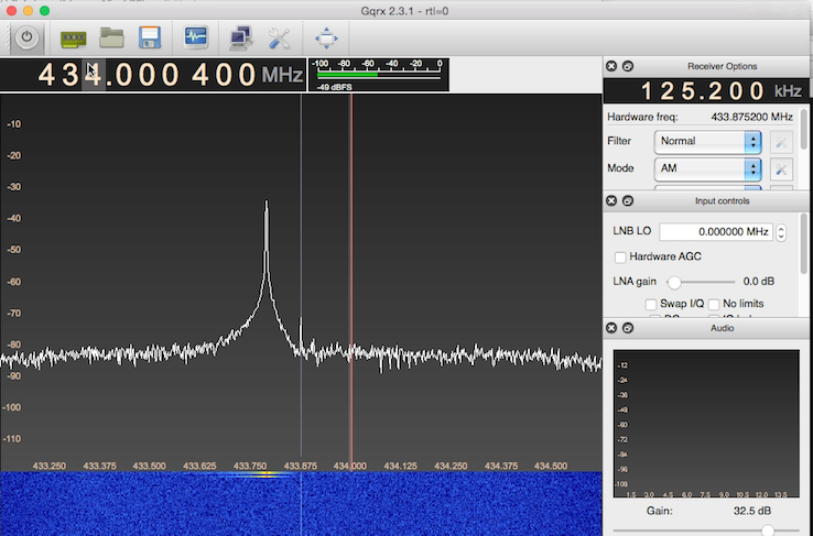
Now that we know the frequency, we must determine the type of modulation used. Modulation is what allows data to be transmitted via radio frequency. I knew based off watching the waterfall view in GQRX that this was Amplitude Modulation (AM), and will explain how below.
We can determine whether the signal is amplitude modulation easily here because it happens to be using something called On-Off Keying, or OOK, which is a type of Amplitude Shift Keying (ASK).
Okay, we're getting into a lot of acronyms, so let's break down the types of modulation we'll see on the first level/layer. First we want to determine the generic modulation (which was Amplitude Modulation in this case):
There are a number of others, but these are the common/most basic modulation schemes we'll see in radio.
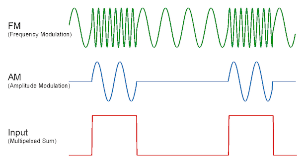
Amplitude modulation simply modulates the amplitude of the signal to send data (so you'll see a high signal sometimes, and a lower or no signal other times).
Frequency modulation actually changes the frequency the signal comes on, so if you're listening to 105.9 FM radio (105.9MHz), the station will actually send audio between 105.895MHz and 105.905MHz depending on the pitch of the sound or the data meant to be revealed. The audio or information is sent by the change in the frequency, aka the modulation of the frequency.

However, since we're dealing with digital information, rather than analog (such as sound), then the modulation will be more discrete (1s and 0s) and use modulation schemes such as:
In this case, if we are using ASK, a type of AM, the signal is likely to only contain 0s and 1s, where no amplitude/signal is sent for 0, and amplitude is high for 1. This makes it easy to interpret the data, and when dealing with Amplitude Shift Keying with no signal or full signal, we have yet another acronym, OOK or On-Off Keying, to describe this modulation. OOK simply means the signal is on (high/1) or off (0/low). You will find this for most common ASK signals.
In many cases, there are additional coding schemes which go on top of this data, such as Manchester coding or NRZ, which produce a switch between high/low signals much more often, however we don't see that in this signal.
Now since we know it's amplitude modulation (AM / ASK / OOK) by the looks of it, we'll use rtl_fm to save the data as AM into a wav file:
rtl_fm -M am -f 434000000 -s 2000000 - | sox -t raw -r 2000000 -e signed-integer -b 16 -c 1 -V1 - doorbell.wav
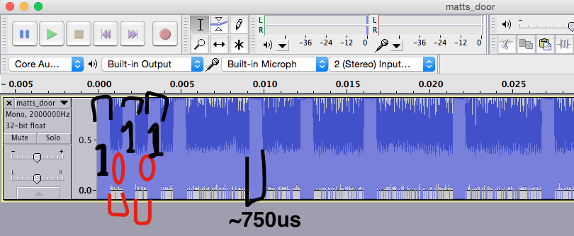
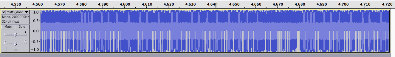
It appears the signal (when looking in Audacity) always sends the same width of the "1"/high signal at 750us (us = microseconds -- 1,000 microseconds in 1 millisecond, and 1,000 milliseconds in 1 second, so 1,000,000 microseconds/us in 1 second)).
The "0"s/lows/no signal also appear to be in blocks of 750us but can be back to back, so you may run into 750us or no signal, or 750 * 2us (1500us), or 750 * 3 (2250us), or many more.
Normally I would take a signal like this and convert it to 1s and 0s. Since 750us seems to be the greatest common divisor, we could just take every 750us of a high signal and call it "1", and every 750us of no signal and call it 0. There's a number of ways to do this with software, likely with something like GNU Radio or possibly rtl_433, but we're going to do everything by hand today.
In this case because I'm lazy and it doesn't really matter if we have a sequence of 1s/0s, since we just need to retransmit a similar signal, no matter how we interpret it, I opt to instead simply send a "1" for 750us, followed by a "0" up until the next "1". This makes it much simpler for me to just locate where all the 1s are, put the time the "1" started in an array, and have code loop through the array to determine how long it should sends all the 0s for (0 will always be for the next location of the "1" - this location of the "1" - 750us). I explain this further in the video above.
Creating the code to trigger this is pretty simply once we've created an array with all the times the "1" (or high) signal begins.
You may be tempted to use a library like VirtualWire or RadioHead to send the RF signal, but don't! These libraries are great when you're creating your own RX and TX devices, but we're only transmitting and we want to be very specific about what we send. These libraries do all sorts of convenient and nice things for you such as adding preambles and CRC checks which help in transmissions where you control the receiver, but will entirely screw up our signal in this case, unless you disable all of those features. The amount of work to disable the features is more work than just bit-banging the signal as we do below I believe.
All of the code is on https://github.com/samyk/dingdong, but here is the relevant part for transmission:
#define TX_PIN 9
#define BIT_PERIOD 700
#define TIMES 22

// here's an array (in seconds) where each "1" begins in the signal
float times[TIMES] = {
  0, .0015, .003, .0045, .0092, .0122, .0161, .0214, .0268, .0298, .0352, .0413, .0436, .0505, .0535, .0574, .062, .0673, .0719, .0757, .0803 };

  /// ... some code

  // go through each "1" bit
  for (int i = 0; i < TIMES-1; i++)
  {
    // calculate microseconds (us) from the second
    int us = times[i] * 1000000;

    // don't delay before the first "1"
    // (this would be a negative amount for the first iteration anwyay)
    // this essentially produces a "0"/low all the way from our last "1" to our current "1"
    if (i != 0)
      delayMicroseconds(us - last - BIT_PERIOD);

    // send a "1" for our BIT_PERIOD which is around 700-800us
    digitalWrite(TX_PIN, HIGH);
    delayMicroseconds(BIT_PERIOD);
    digitalWrite(TX_PIN, LOW);

    last = us;
  }

  /// more awesome code
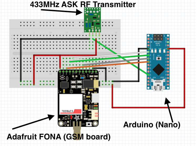
I go into the Arduino a little bit in the video, however I've created a Fritzing sketch below so you can see how everything is wired up.
Now that we know the signal is 434MHz and ASK, we can get a simple ASK transmitter on 434MHz for just a few dollars and use it to "bit bang" our signal. If you're not using the FONA/GSM board, simply ignore the FONA and its connections.
The software you need to load on the Arduino is on github here: https://github.com/samyk/dingdong
You do need to power the Arduino (easy by connecting USB to it), as well as connecting USB to the FONA and a 3.7v Lion/LiPo battery to the FONA and leave it outside the location of the doorbell. Don't worry as the FONA USB connection simply charges the battery. It's silly, I know, but it's necessary. If just running temporary, USB batteries work great too.
I actually left it across the street and it worked great!
Then, you simply send an SMS message with the word "doorbell" to the device (case sensitive), and it will cause the Arduino to transmit the signal we created and ring the doorbell! Awesome!
Run. Seriously, run!!!
Feel free to contact me with any questions!
Follow @SamyKamkar on Twitter!
You can see more of my projects at https://samy.pl or contact me at code@samy.pl.